

Multi-Position Motor Drive ・ Compact Gate Valve MEX-LD-AZ Series
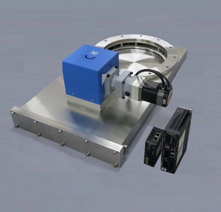
Our original drive system has superior cost performance
| 1.Low-price | Automatic pressure control is made low-priced |
|---|---|
| 2.High-performance | Adopt high performance stepping motor and driver |
| 3.High-functionality | Full closing, Multi-position control, Auto pressure control ABZO sensor enables battery-less absolute system Motor position-selected (three-position) |
select from three types
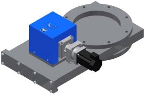
MEX-LD-AZ-R
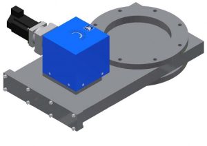
MEX-LD-AZ-L
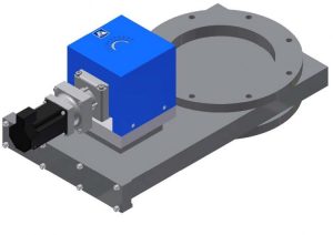
MEX-LD-AZ-F
Features
- Full closing (shut-off valve) and conductance adjustment can be done by one unit.
- The stop position accuracy can be reproduced easily by adopting “Highly precise Gear head”.
- This valve can be stopped at any position of maximum 14- position and at the fully closed, fully open.
Position settings are available from the support source. Can be easily installed on a PC. - By adding optional components for control, automatic pressure control valve can be used as.
- The valve disc position can be confirmed from the outside by its angle indicator.
- The ability to select the motor position can be flexible to a variety of layouts, and utilize the space to install the exhaust system.
- Fully closed and fully open position detecting sensor can be equipped as an option
Basic specification
| STD FLANGE | JIS・ISO・CF |
|---|---|
| Leak Rate | Housing 1×10-11 Pa・m3/s > Valve seat 1×10⁻¹⁰ Pa・m3/s > |
| Pressure Range | 105 ~ 10-6 Pa |
| Stem Seal | Viton O-ring |
| Main Material | SUS304 |
| Diameter | 70 ~ 400(mm) |
|---|---|
| Control system | Hybrid control system αSTEP ※1 |
| Power Specifications | DC power supply DC24V/DC48V 3.45A(3.7A)※3 AC power supply ※2 Single-phase AC 100-120V 5.4 A Single-phase AC 200-240V 3.3A Three-phase AC 200-240V 2.0A |
- Subject to change without any notice
- Please contact us as we can manufacture special sizes and special specifications.
- The diameter is limited to the mounting direction. Please inquire our sales.
※1 Hybrid control system αSTEP: Original control of Oriental Motor Co., Ltd. that combines the advantages of “open
loop control” and “closed loop control”.
※2 A driver with AC power supply specifications requires a separate DC24V 0.25A (0.5A) * 3 as a power supply for the
control circuit.
※3 ( ) Is the current value when using a motor with a brake.
Valve model
◆Standard motor specifications
・MEX-□-LD-AZ-△-KD Power input:DC24V/DC48V
・MEX-□-LD-AZ-△-AD Power input:AC single-phase 100-120V
・MEX-□-LD-AZ-△-CD Power input:AC single-phase / three-phase 200-240V
◆Motor specifications with brake
・MEX-□-LD-AZBr-△-KD Power input:DC24V/DC48V
・MEX-□-LD-AZBr-△-AD Power input:AC single-phase 100-120V
・MEX-□-LD-AZBr-△-CD Power input:AC single-phase / three-phase 200-240V
□:Flange type and diameter △:Motor position (R / L / F)
System configuration
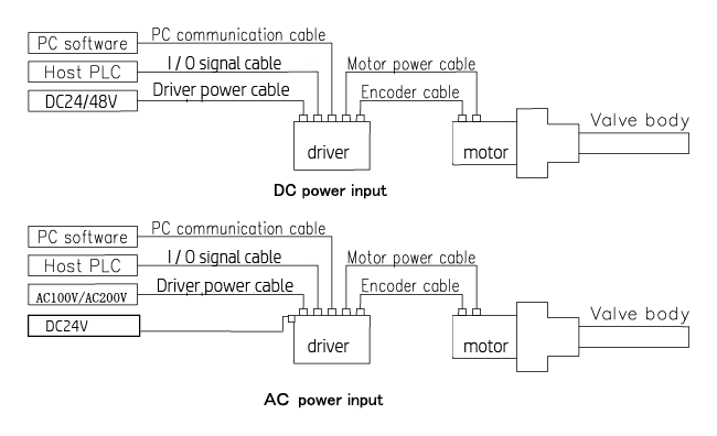
※Included in the valve unit:Valve body, motor, driver
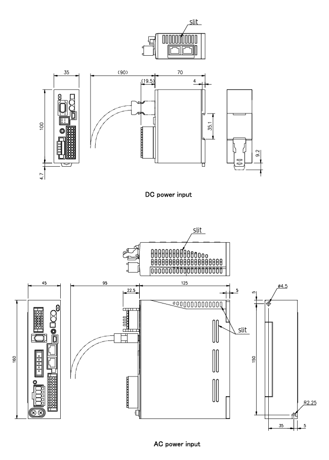
Attached driver dimensional drawing
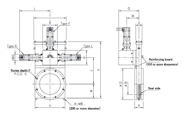
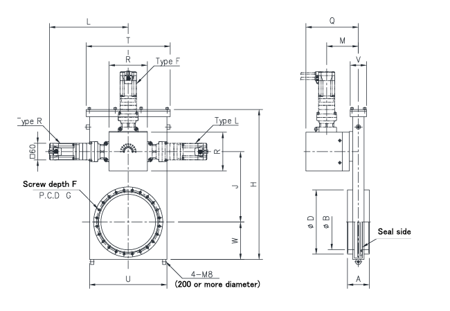
Dimensions of MEX-JIS-LD-AZ Series
| Unit in:mm | ||||||||
| Diameter | 80 | 100 | 150 | 200 | 250 | 300 | 350 | 400 |
| MOD No | 16709□□ | 16710□□ | 16711□□ | 16712□□ | 16713□□ | 16714□□ | 16714□□ | 16715□□ |
| Model | MEX-80JIS-LD-AZ-□□ | MEX-100JIS-LD- AZ-□□ | MEX-150JIS-LD- AZ-□□ | MEX-200JIS-LD- AZ-□□ | MEX-250JIS-LD- AZ-□□ | MEX-300JIS-LD- AZ-□□ | MEX-350JIS-LD- AZ-□□ | MEX-400JIS-LD- AZ-□□ |
| A | 70 | 70 | 80 | 80 | 85 | 85 | 100 | 100 |
| B | 80 | 100 | 150 | 200 | 250 | 300 | 350 | 400 |
| D | 160 | 185 | 235 | 300 | 350 | 400 | 450 | 520 |
| n—E | 4-M10 | 8-M10 | 8-M10 | 8-M12 | 12-M12 | 12-M12 | 12-M12 | 12-M16 |
| F | 14 | 14 | 14 | 15 | 16 | 16 | 18 | 18 |
| G | 135 | 160 | 210 | 270 | 320 | 370 | 420 | 480 |
| H | 314.5 | 314.5 | 401.5 | 541 | 654 | 752 | 916 | 1023 |
| J | 150 | 150 | 192 | 254 | 305 | 356 | 433 | 483 |
| L | 271.5 | 271.5 | 271.5 | 288.5 | 288.5 | 288.5 | 288.5 | 288.5 |
| M | 105 | 105 | 105 | 116 | 120 | 121 | 128 | 129 |
| Q | 174 | 174 | 174 | 192 | 196 | 197 | 204 | 205 |
| R | 110 | 110 | 110 | 140 | 140 | 140 | 140 | 140 |
| T | 180 | 180 | 235 | 308 | 380 | 430 | 512 | 560 |
| U | 158 | 158 | 210 | 284 | 348 | 402 | 480 | 528 |
| V | 60 | 60 | 60 | 60 | 72 | 72 | 80 | 82 |
| W | 79 | 79 | 99 | 135 | 165 | 190 | 231 | 255 |
Note1:The above Flanges are accordance with older JIS B2290 Vacuum Flange for Vacuum Equipment (Flange for
affiliated book maintenance)
Note2:A motor position type enters in () of form. (It chooses from three positions)
Note3:An attachment posture is limited depending on a diameter. Please ask to business for details.
Note4:Be careful for more than the screw depth of a flange not to screw in the screw for valve attachment.
※To im prove this specification may change without notice.
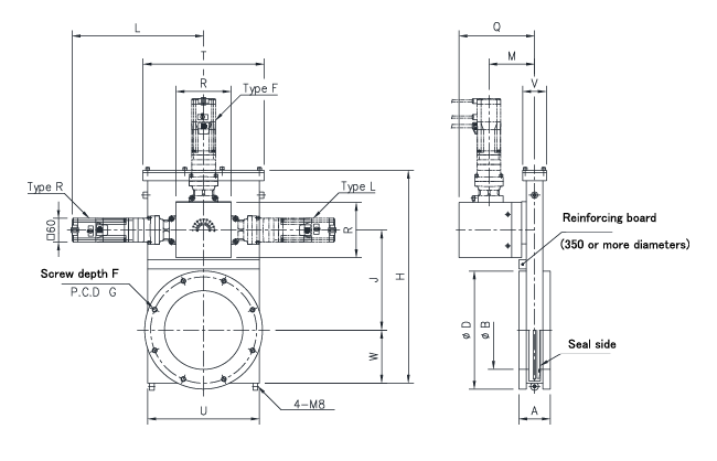
Dimensions of MEX-ISO-LD-AZ Series
| Unit in:mm | |||||||
| Diameter | 80 | 100 | 150 | 200 | 250 | 300 | 400 |
| MOD No | 16767□□ | 16768□□ | 16770□□ | 16771□□ | 16772□□ | 16773□□ | 16774□□ |
| Model | MEX-80ISO-LD- AZ-□□ | MEX-100ISO-LD- AZ-□□ | MEX-150ISO-LD- AZ-□□ | MEX-200ISO-LD- AZ-□□ | MEX-250ISO-LD- AZ-□□ | MEX-300ISO-LD- AZ-□□ | MEX-400ISO-LD- AZ-□□ |
| A | 70 | 70 | 80 | 80 | 85 | 85 | 100 |
| B | 80 | 100 | 150 | 200 | 250 | 300 | 400 |
| C | 83 | 102 | 153 | 213 | 261 | 318 | 400 |
| D | 145 | 165 | 225 | 285 | 335 | 425 | 510 |
| n—E | 8-M8 | 8-M8 | 8-M10 | 12-M10 | 12-M10 | 12-M12 | 16-M12 |
| F | 14 | 14 | 14 | 15 | 16 | 16 | 18 |
| G | 125 | 145 | 200 | 260 | 310 | 395 | 480 |
| H | 314.5 | 314.5 | 401.5 | 541 | 654 | 752 | 1023 |
| J | 150 | 150 | 192 | 254 | 305 | 356 | 483 |
| L | 271.5 | 271.5 | 271.5 | 288.5 | 288.5 | 288.5 | 288.5 |
| M | 105 | 105 | 105 | 116 | 120 | 121 | 129 |
| Q | 174 | 174 | 174 | 192 | 196 | 197 | 205 |
| R | 110 | 110 | 110 | 140 | 140 | 140 | 140 |
| T | 180 | 180 | 235 | 308 | 380 | 430 | 560 |
| U | 158 | 158 | 210 | 284 | 348 | 402 | 528 |
| V | 60 | 60 | 60 | 60 | 72 | 72 | 82 |
| W | 79 | 79 | 99 | 135 | 165 | 190 | 255 |
Note1:The above Flanges are accordance with ISO 1609 Vacuum technology Flange
Note2:A motor position type enters in () of form. (It chooses from three positions)
Note3:An attachment posture is limited depending on a diameter. Please ask to business for details.
Note4:Be careful for more than the screw depth of a flange not to screw in the screw for valve attachment.
※To improve this specification may change without notice.
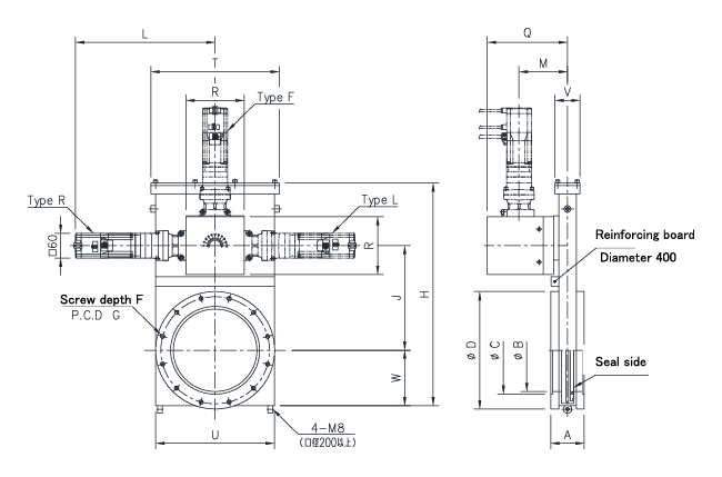
Dimensions of MEX-CF-LD-AZ Series
| Unit in:mm | |||||
| Diameter | 70 | 100 | 150 | 200 | 250 |
| MOD No | 16743□□ | 16744□□ | 16745□□ | 16746□□ | 16747□□ |
| Model | MEX-70CF-LD- AZ-□□ | MEX-100CF-LD- AZ-□□ | MEX-150CF-LD- AZ-□□ | MEX-200CF-LD- AZ-□□ | MEX-250CF-LD- AZ-□□ |
| CF flange nominal | CF114 | CF152 | CF203 | CF253 | CF305 |
| A | 70 | 70 | 80 | 80 | 100 |
| B | 70 | 100 | 150 | 200 | 250 |
| D | 113.5 | 151.6 | 202.4 | 253.2 | 306 |
| n—E | 8-M8 | 16-M8 | 20-M8 | 24-M8 | 32-M8 |
| F | 14 | 14 | 14 | 16 | 23 |
| G | 92.1 | 130.2 | 181 | 231.8 | 284 |
| H | 314.5 | 314.5 | 401.5 | 541 | 654 |
| J | 150 | 150 | 192 | 254 | 305 |
| L | 271.5 | 271.5 | 271.5 | 288.5 | 288.5 |
| M | 105 | 105 | 105 | 116 | 120 |
| Q | 174 | 174 | 174 | 192 | 196 |
| R | 110 | 110 | 110 | 140 | 140 |
| T | 180 | 180 | 235 | 308 | 380 |
| U | 158 | 158 | 210 | 284 | 348 |
| V | 60 | 60 | 60 | 60 | 72 |
| W | 79 | 79 | 99 | 135 | 165 |
Note1:The above Flanges are accordance with ISO 3669 Vacuum technology-Bakable Flange
Note2:A motor position type enters in () of form. (It chooses from three positions)
Note3:An attachment posture is limited depending on a diameter. Please ask to business for details.
Note4:Be careful for more than the screw depth of a flange not to screw in the screw for valve
attachment.
※To improve this specification may change without notice.
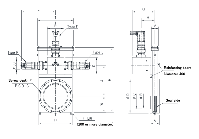
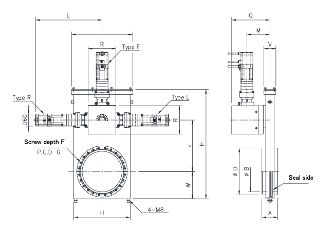
Dimensions of MEX-JIS-LD-AZBr Series
| Unit in:mm | ||||||||
| Diameter | 80 | 100 | 150 | 200 | 250 | 300 | 350 | 400 |
| MOD No | 16709□□ | 16710□□ | 16711□□ | 16712□□ | 16713□□ | 16714□□ | 16714□□ | 16715□□ |
| Model | MEX-80JIS-LD-AZBr-□□ | MEX-100JIS-LD-AZBr-□□ | MEX-150JIS-LD-AZBr-□□ | MEX-200JIS-LD-AZBr-□□ | MEX-250JIS-LD-AZBr-□□ | MEX-300JIS-LD-AZBr-□□ | MEX-350JIS-LD-AZBr-□□ | MEX-400JIS-LD-AZBr-□□ |
| A | 70 | 70 | 80 | 80 | 85 | 85 | 100 | 100 |
| B | 80 | 100 | 150 | 200 | 250 | 300 | 350 | 400 |
| D | 160 | 185 | 235 | 300 | 350 | 400 | 450 | 520 |
| n—E | 4-M10 | 8-M10 | 8-M10 | 8-M12 | 12-M12 | 12-M12 | 12-M12 | 12-M16 |
| F | 14 | 14 | 14 | 15 | 16 | 16 | 18 | 18 |
| G | 135 | 160 | 210 | 270 | 320 | 370 | 420 | 480 |
| H | 314.5 | 314.5 | 401.5 | 541 | 654 | 752 | 916 | 1023 |
| J | 150 | 150 | 192 | 254 | 305 | 356 | 433 | 483 |
| L | 317.5 | 317.5 | 317.5 | 334.5 | 334.5 | 334.5 | 334.5 | 334.5 |
| M | 105 | 105 | 105 | 116 | 120 | 121 | 128 | 129 |
| Q | 174 | 174 | 174 | 192 | 196 | 197 | 204 | 205 |
| R | 110 | 110 | 110 | 140 | 140 | 140 | 140 | 140 |
| T | 180 | 180 | 235 | 308 | 380 | 430 | 512 | 560 |
| U | 158 | 158 | 210 | 284 | 348 | 402 | 480 | 528 |
| V | 60 | 60 | 60 | 60 | 72 | 72 | 80 | 82 |
| W | 79 | 79 | 99 | 135 | 165 | 190 | 231 | 255 |
Note1:The above Flanges are accordance with older JIS B2290 Vacuum Flange for Vacuum Equipment (Flange for
affiliated book maintenance)
Note2:A motor position type enters in () of form. (It chooses from three positions)
Note3:An attachment posture is limited depending on a diameter. Please ask to business for details.
Note4:Be careful for more than the screw depth of a flange not to screw in the screw for valve attachment.
※To im prove this specification may change without notice.
Dimensions of MEX-ISO-LD-AZBr Series
| Unit in:mm | |||||||
| Diameter | 80 | 100 | 150 | 200 | 250 | 300 | 400 |
| MOD No | 16767□□ | 16768□□ | 16770□□ | 16771□□ | 16772□□ | 16773□□ | 16774□□ |
| Model | MEX-80ISO-LD-AZBr-□□ | MEX-100ISO-LD-AZBr-□□ | MEX-150ISO-LD-AZBr-□□ | MEX-200ISO-LD-AZBr-□□ | MEX-250ISO-LD-AZBr-□□ | MEX-300ISO-LD-AZBr-□□ | MEX-400ISO-LD-AZBr-□□ |
| A | 70 | 70 | 80 | 80 | 85 | 85 | 100 |
| B | 80 | 100 | 150 | 200 | 250 | 300 | 400 |
| C | 83 | 102 | 153 | 213 | 261 | 318 | 400 |
| D | 145 | 165 | 225 | 285 | 335 | 425 | 510 |
| n—E | 8-M8 | 8-M8 | 8-M10 | 12-M10 | 12-M10 | 12-M12 | 16-M12 |
| F | 14 | 14 | 14 | 15 | 16 | 16 | 18 |
| G | 125 | 145 | 200 | 260 | 310 | 395 | 480 |
| H | 314.5 | 314.5 | 401.5 | 541 | 654 | 752 | 1023 |
| J | 150 | 150 | 192 | 254 | 305 | 356 | 483 |
| L | 317.5 | 317.5 | 317.5 | 334.5 | 334.5 | 334.5 | 334.5 |
| M | 105 | 105 | 105 | 116 | 120 | 121 | 129 |
| Q | 174 | 174 | 174 | 192 | 196 | 197 | 205 |
| R | 110 | 110 | 110 | 140 | 140 | 140 | 140 |
| T | 180 | 180 | 235 | 308 | 380 | 430 | 560 |
| U | 158 | 158 | 210 | 284 | 348 | 402 | 528 |
| V | 60 | 60 | 60 | 60 | 72 | 72 | 82 |
| W | 79 | 79 | 99 | 135 | 165 | 190 | 255 |
Note1:The above Flanges are accordance with ISO 1609 Vacuum technology Flange
Note2:A motor position type enters in () of form. (It chooses from three positions)
Note3:An attachment posture is limited depending on a diameter. Please ask to business for details.
Note4:Be careful for more than the screw depth of a flange not to screw in the screw for valve attachment.
※To improve this specification may change without notice.
Dimensions of MEX-CF-LD-AZBr Series
| Unit in:mm | |||||
| Diameter | 70 | 100 | 150 | 200 | 250 |
| MOD No | 16743□□ | 16744□□ | 16745□□ | 16746□□ | 16747□□ |
| Model | MEX-70CF-LD-AZBr-□□ | MEX-100CF-LD-AZBr-□□ | MEX-150CF-LD-AZBr-□□ | MEX-200CF-LD-AZBr-□□ | MEX-250CF-LD-AZBr-□□ |
| CF flange nominal | CF114 | CF152 | CF203 | CF253 | CF305 |
| A | 70 | 70 | 80 | 80 | 100 |
| B | 70 | 100 | 150 | 200 | 250 |
| D | 113.5 | 151.6 | 202.4 | 253.2 | 306 |
| n—E | 8-M8 | 16-M8 | 20-M8 | 24-M8 | 32-M8 |
| F | 14 | 14 | 14 | 16 | 23 |
| G | 92.1 | 130.2 | 181 | 231.8 | 284 |
| H | 314.5 | 314.5 | 401.5 | 541 | 654 |
| J | 150 | 150 | 192 | 254 | 305 |
| L | 317.5 | 317.5 | 317.5 | 334.5 | 334.5 |
| M | 105 | 105 | 105 | 116 | 120 |
| Q | 174 | 174 | 174 | 192 | 196 |
| R | 110 | 110 | 110 | 140 | 140 |
| T | 180 | 180 | 235 | 308 | 380 |
| U | 158 | 158 | 210 | 284 | 348 |
| V | 60 | 60 | 60 | 60 | 72 |
| W | 79 | 79 | 99 | 135 | 165 |
Note1 The above Flanges are accordance with ISO 3669 Vacuum technology-Bakable Flange
Note2:A motor position type enters in () of form. (It chooses from three positions)
Note3:An attachment posture is limited depending on a diameter. Please ask to business for details.
Note4:Be careful for more than the screw depth of a flange not to screw in the screw for valve
attachment.
※To improve this specification may change without notice.