

Butterfly Valve AXONⅡSeries
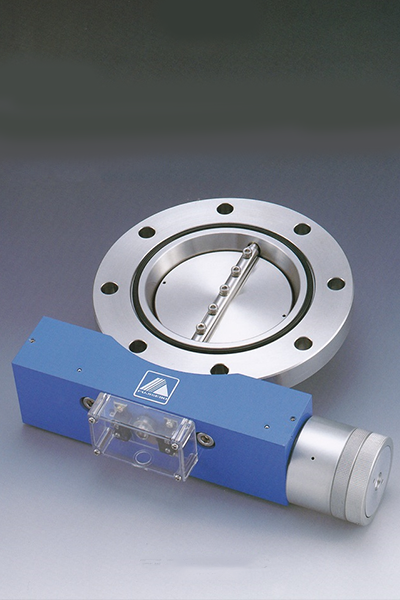
1,000,000 cycles and two years guarantee
High performance
- ◇ 1,000,000 cycles and two years guarantee
Two worth works with one valve
- ◇ It can be operated in the 2 position of the valve opening is 0 degrees to 45 degrees and 90 degrees ( fully open ) , so it is possible for throw exhaust and high speed exhaust at one valve.
- ◆ Fully closed and fully open for air cylinder , and the valve opening degree is a two-step structure of which is provided an air cylinder that can be set to any in the range of 0 to 45 degrees .
Adopt a double cylinder system of patent mechanism ( Pneumatic type )
- ◇ By adopting a double air cylinder method, an air thrust doubles during valve fully open, More impact force by the air damper mechanism have been alleviated.
- ◆ Double cylinder system is provided a bypass flow and the assist chamber in the cylinder
- ◇ The bypass flow is connected with the assist chamber from the valve fully open side cylinder chamber The diameter is reduced enough than the diameter of the air inlet.
- ◆ Piston movement will begin before sufficient air is supplied to assist chamber by this mechanism.
When the valve body is fully opened, the pressure in the assist chamber becomes negative, so assist chamber will alleviate the impact force as air cushion.
Unchanged price , The price that it is easy to adopt
- ◇ New series can be immediately exchange for the old series and the same dimensions.
- ◆ It’s the price quite more profitable than the price for 2 valves, so it’ll be cost cutting of an exhaust system.
Basic specification
| STD Flange | JIS・NW・ISO・CF |
|---|---|
| Leak Rate | <1×10⁻⁹Pam3/s |
| Pressure Range | 105~10-6Pa |
| Disc seal | Viton O-ring |
| Diameter | 25A~350A |
|---|---|
| Gas contact material | SUS304 |
| Actuating air pressure | 0.4~0.6MPa G |
| Actuating air pressure | Viton O-ring two-tier |
- ※ Equipped with micro- switch of the full closed and full open for switching signal as standard.
When an intermediate position signal is required, it can manufacture as an option. - ※ The following condition is necessary to maintain the performance of this valve.
・ Periodic replacement of the valve disc O-ring
・ Periodic grease up the sealing surface of the valve - ※ For more diameter 150A is moved to an intermediate position will be operation from the fully open position.
It’s also possible to manufacture the way which makes move from full close, so please inquire. - ※ Other special specification manufacture is also available , Please contact us.
- ※ Subject to change without any notice.
※To improve this specification may change without notice.
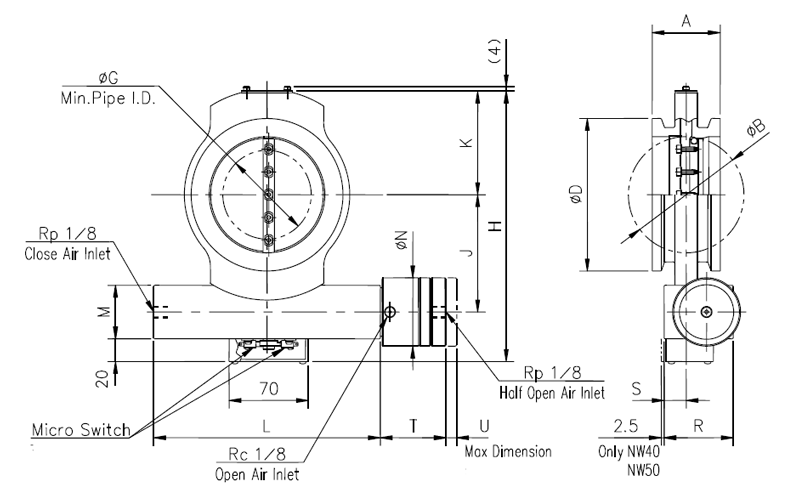
Dimensions of BV-JIS AXONⅡ Series
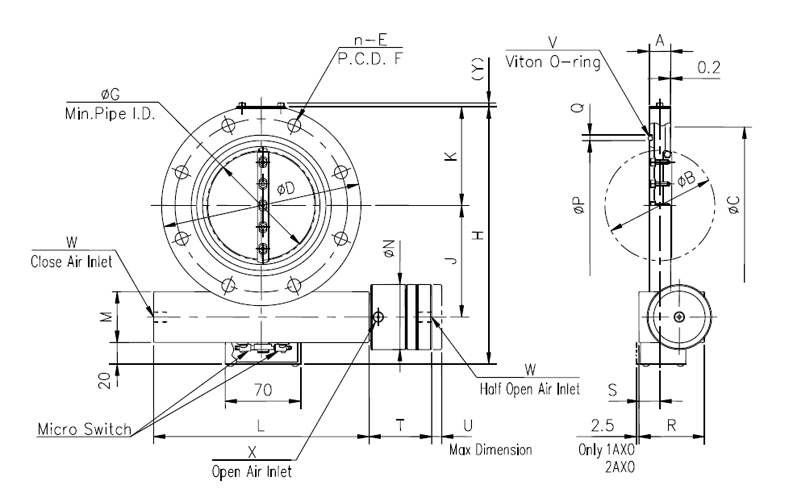
| Unit in:mm | ||||||||||
| Model | BV-1AXONⅡ | BV-2AXONⅡ | BV-2.5AXONⅡ | BV-3AXONⅡ | BV-4AXONⅡ | BV-6AXONⅡ | BV-8AXONⅡ | BV-10AXONⅡ | BV-12AXONⅡ | BV-14AXONⅡ |
| MOD No. | 10205□□ | 10207□□ | 10208□□ | 10209□□ | 10210□□ | 10211□□ | 10212□□ | 10213□□ | 10214□□ | 10215□□ |
| A | 20 | 20 | 20 | 20 | 20 | 26 | 40 | 40 | 45 | 50 |
| B | 34 | 52 | 68 | 81 | 104 | 158 | 209 | 258 | 308 | 357 |
| C | 58 | 88 | 105 | 120 | 145 | 190 | 250 | 302 | 352 | 402 |
| D | 90 | 120 | 145 | 160 | 185 | 235 | 300 | 350 | 400 | 450 |
| n—E | 4-φ10 | 4-φ10 | 4-φ12 | 4-φ12 | 8-φ12 | 8-φ12 | 8-φ15 | 12-φ15 | 12-φ15 | 12-φ15 |
| F | 70 | 100 | 120 | 135 | 160 | 210 | 270 | 320 | 370 | 420 |
| G | 33 | 52 | 67 | 80 | 102 | 154 | 206 | 254 | 303 | 354 |
| H | 138 | 168.5 | 198 | 212 | 237.5 | 299 | 380 | 446 | 496 | 552 |
| J | 55 | 70 | 83 | 90.5 | 103 | 127.5 | 165 | 200 | 225 | 240 |
| K | 43 | 58.5 | 71.5 | 78 | 91 | 116.5 | 148.5 | 173.5 | 198.5 | 224 |
| L | 170 | 170 | 200 | 200 | 200 | 270 | 350 | 380 | 380 | 584 |
| M | 40 | 40 | 47 | 47 | 47 | 70 | 93 | 105 | 105 | 136 |
| N | 60 | 60 | 76 | 76 | 76 | 88 | 130 | 145 | 145 | 180 |
| P | 40 | 70 | 85 | 100 | 120 | 175 | 225 | 275 | 325 | 380 |
| Q | 5 | 5 | 5 | 5 | 5 | 5 | 8 | 8 | 8 | 8 |
| R | 55 | 55 | 61 | 61 | 61 | 79 | 107.5 | 123.5 | 123.5 | 185 |
| S | 15.5 | 15.5 | 19.5 | 19.5 | 19.5 | 22 | 23 | 23 | 23 | 37 |
| T | 55 | 55 | 58 | 58 | 58 | 69 | 90 | 100 | 100 | 135 |
| U | 9.5 | 9.5 | 9.5 | 9.5 | 9.5 | 12.5 | 23.5 | 31.5 | 31.5 | 55 |
| V | V40 | V70 | V85 | V100 | V120 | V175 | V225 | V275 | V325 | V380 |
| W | Rp1/8 | Rp1/8 | Rp1/8 | Rp1/8 | Rp1/8 | Rc1/4 | Rc1/4 | Rc1/4 | Rc1/4 | Rc1/4 |
| X | Rc1/8 | Rc1/8 | Rc1/8 | Rc1/8 | Rc1/8 | Rc1/4 | Rc1/4 | Rc1/4 | Rc1/4 | Rc1/4 |
| Y | 4 | 4 | 4 | 4 | 4 | 4 | 4 | 4 | 4 | 5 |
Note1:The above Flanges are accordance with older JIS B2290 Vacuum Flange for Vacuum Equipment (Flange for affiliated
book maintenance)
Dimensions of BV-ISO AXON Series
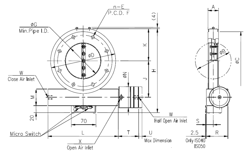
| Unit in:mm | ||||||||
| Model | BV-ISO40AXONⅡ | BV-ISO50AXONⅡ | BV-ISO63AXONⅡ | BV-ISO80AXONⅡ | BV-ISO100AXONⅡ | BV-ISO160AXONⅡ | BV-ISO200AXONⅡ | BV-ISO250AXONⅡ |
| MOD No. | 10965□□ | 10966□□ | 10967□□ | 10967□□ | 10968□□ | 10970□□ | 10971□□ | 10972□□ |
| A | 30 | 30 | 30 | 30 | 30 | 50 | 50 | 50 |
| B | 34 | 52 | 68 | 81 | 104 | 158 | 209 | 258 |
| C | 100 | 110 | 130 | 145 | 165 | 225 | 285 | 335 |
| D | 120 | 120 | 145 | 160 | 185 | 235 | 300 | 350 |
| n—E | 4-φ9 | 4-φ9 | 4-φ9 | 8-φ9 | 8-φ9 | 8-φ11 | 12-φ11 | 12-φ11 |
| F | 80 | 90 | 110 | 125 | 145 | 200 | 260 | 310 |
| G | 23 | 47 | 62 | 76 | 100 | 148 | 203 | 251 |
| H | 168.5 | 168.5 | 198 | 212 | 237.5 | 299 | 380 | 446 |
| J | 70 | 70 | 83 | 90.5 | 103 | 127.5 | 165 | 200 |
| K | 58.5 | 58.5 | 71.5 | 78 | 91 | 116.5 | 148.5 | 173.5 |
| L | 170 | 170 | 200 | 200 | 200 | 270 | 350 | 380 |
| M | 40 | 40 | 47 | 47 | 47 | 70 | 93 | 105 |
| N | 60 | 60 | 76 | 76 | 76 | 88 | 130 | 145 |
| R | 55 | 55 | 61 | 61 | 61 | 79 | 107.5 | 123.5 |
| S | 15.5 | 15.5 | 19.5 | 19.5 | 19.5 | 22 | 23 | 23 |
| T | 55 | 55 | 58 | 58 | 58 | 69 | 90 | 100 |
| U | 9.5 | 9.5 | 9.5 | 9.5 | 9.5 | 12.5 | 23.5 | 31.5 |
| W | Rp1/8 | Rp1/8 | Rp1/8 | Rp1/8 | Rp1/8 | Rc1/4 | Rc1/4 | Rc1/4 |
| X | Rp1/8 | Rp1/8 | Rp1/8 | Rp1/8 | Rp1/8 | Rc1/4 | Rc1/4 | Rc1/4 |
Note1:The above Flanges are accordance with ISO 1609 Vacuum technology Flange
Dimensions of BV-CF AXONⅡ Series
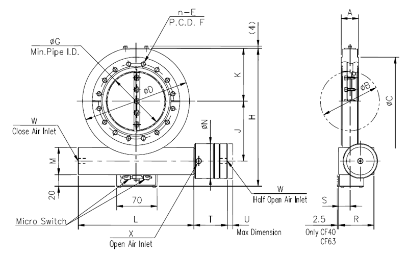
| Unit in:mm | ||||||
| Model | BV-CF40AXONⅡ | BV-CF63AXONⅡ | BV-CF100AXONⅡ | BV-CF160AXONⅡ | BV-CF200AXONⅡ | BV-CF250AXONⅡ |
| MOD No. | 10940□□ | 10942□□ | 10944□□ | 10945□□ | 10947□□ | 10948□□ |
| A | 30 | 30 | 30 | 50 | 50 | 50 |
| B | 34 | 52 | 104 | 158 | 209 | 258 |
| C | 69.4 | 113.5 | 151.6 | 202.4 | 253.2 | 305.0 |
| D | 90 | 120 | 185 | 235 | 300 | 350 |
| n—E | 6-M6 | 8-M8 | 16-M8 | 20-M8 | 24-M8 | 32-M8 |
| F | 58.7 | 92.1 | 130.2 | 181 | 231.8 | 284 |
| G | 23 | 47 | 100 | 148 | 203 | 251 |
| H | 138 | 168.5 | 237.5 | 299 | 380 | 446 |
| J | 55 | 70 | 103 | 127.5 | 165 | 200 |
| K | 43 | 58.5 | 91 | 116.5 | 148.5 | 173.5 |
| L | 170 | 170 | 200 | 270 | 350 | 380 |
| M | 40 | 40 | 47 | 70 | 93 | 105 |
| N | 60 | 60 | 76 | 88 | 130 | 145 |
| R | 55 | 55 | 61 | 79 | 107.5 | 123.5 |
| S | 15.5 | 15.5 | 19.5 | 22 | 23 | 23 |
| T | 55 | 55 | 58 | 69 | 90 | 100 |
| U | 9.5 | 9.5 | 9.5 | 12.5 | 23.5 | 31.5 |
| W | Rp1/8 | Rp1/8 | Rp1/8 | Rc1/4 | Rc1/4 | Rc1/4 |
| X | Rp1/8 | Rp1/8 | Rp1/8 | Rc1/4 | Rc1/4 | Rc1/4 |
Note1:The above Flanges are accordance with ISO/TS 3669-2 Vacuum technology-Bakable flanges-Part2:Dimension of knife-edge flanges
Note2:No Groove for leakage detection no CF 40
Dimensions of BV-NW AXONⅡ Series
| Unit in:mm | ||||||
| Model | BV-NW40AXONⅡ | BV-NW50AXONⅡ | BV-NW63AXONⅡ | BV-NW80AXONⅡ | BV-NW100AXONⅡ | |
| MOD No. | 10224□□ | 10225□□ | 10226□□ | 10227□□ | 10228□□ | |
| A | 40 | 40 | 40 | 60 | 60 | |
| B | 34 | 52 | 68 | 81 | 104 | |
| D | 55 | 75 | 87 | 114 | 134 | |
| G | 0 | 36 | 56 | 55 | 84 | |
| H | 138 | 168.5 | 198 | 212 | 237.5 | |
| J | 55 | 70 | 83 | 90.5 | 103 | |
| K | 43 | 58.5 | 71.5 | 78 | 91 | |
| L | 170 | 170 | 200 | 200 | 200 | |
| M | 40 | 40 | 47 | 47 | 47 | |
| N | 60 | 60 | 76 | 76 | 76 | |
| R | 55 | 55 | 61 | 61 | 61 | |
| S | 15.5 | 15.5 | 19.5 | 19.5 | 19.5 | |
| T | 55 | 55 | 58 | 58 | 58 | |
| U | 9.5 | 9.5 | 9.5 | 9.5 | 9.5 | |
Note1:When installing, use Fuji Technology made Multi-Clump. In case of using other Clumps, there are some cases where installing is impossible owing to their shape.
Figure of BV-AXONⅡseries
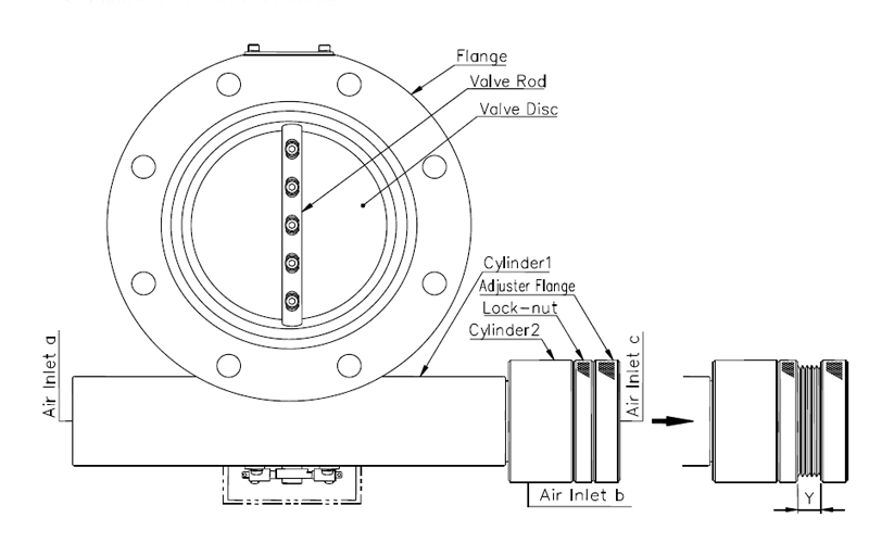
How to adjust opening angle of Valve Disc
By pulling out the Adjuster Flange from the cylinder 2 as shown above , the opening angle of valve Disc can be set in the range of 45°~0°.
The relation between Y and the valve opening angle is shown in Table-1. This table was prepared by using calculated values, so it may sometime differ from an actual valve opening angle.
Table-1
| (unit:mm) | |||||
|
Bore / Angle |
45° |
30° |
15° |
5° |
0° |
|
Below 100A |
0 |
3.1 |
6.3 |
8.4 |
9.4 |
|
150A |
0 |
4.6 |
8.8 |
11.6 |
13.0 |
|
200A |
0 |
7.8 |
15.6 |
20.9 |
23.5 |
|
250A・300A |
0 |
10.5 |
21.0 |
28.0 |
31.5 |
|
350A |
0 |
18.3 |
36.7 |
48.9 |
55.0 |
* The valve opening 0° is an adjustment of cylinder 2, and it is unrelated to the switching action of cylinder 1.
* Y denotes the length when Lock-nut was fixed after Adjuster Flange was pulled out.
How to connect air piping
Connect the air pressure of 0.4 ~ 0.6MPa G to Inlet a, b, c.
Table2 shows relationship between the valve state and the combination of whether air is let IN or OUT at each Air Inlet.
Table-2
|
Valve state / Air inlet |
Inlet a |
Inlet b |
Inlet c |
|
Full close |
IN |
OUT |
OUT |
|
Full open |
OUT |
IN |
* Note |
|
Intermediate |
IN |
OUT |
IN |
*)IN or Out,Either will do.